

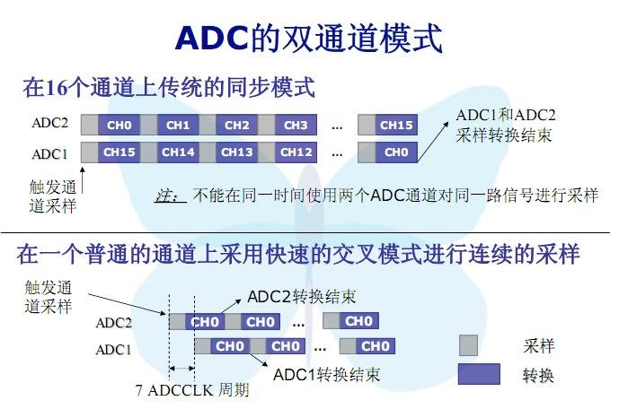
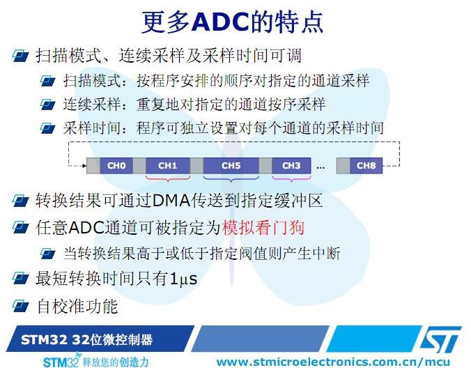
(一) STM32 ADC 模块介绍

下载 (52.26 KB)
下载 (69.24 KB)
(二) 程序编写 (1) 设置 ADC 的地址 #define ADC1_DR_Address ((u32)0x4001244C)
(2) 初始化 DMA 和 ADC 模块与应用程序 / DMA channel1 configuration ———————————————-/ DMA_DeInit(DMA1_Channel1); DMA_InitStructure.DMA_PeripheralBaseAddr = ADC1_DR_Address; // 外设地址 DMA_InitStructure.DMA_MemoryBaseAddr = (u32)&ADC_ConvertedValue; // 内存地址 DMA_InitStructure.DMA_DIR = DMA_DIR_PeripheralSRC; // DMA 传输方向单向 DMA_InitStructure.DMA_BufferSize = 1; // 设置DMA在传输时缓冲区的长度 word DMA_InitStructure.DMA_PeripheralInc = DMA_PeripheralInc_Disable; //设置DMA外设递增模式 DMA_InitStructure.DMA_MemoryInc = DMA_MemoryInc_Disable; // 设置DMA内存递增模式 DMA_InitStructure.DMA_PeripheralDataSize = DMA_PeripheralDataSize_HalfWord; // 外设数据字长 DMA_InitStructure.DMA_MemoryDataSize = DMA_MemoryDataSize_HalfWord; //内存数据字长 DMA_InitStructure.DMA_Mode = DMA_Mode_Circular; // 设置传输模式连续不断的循环模式 DMA_InitStructure.DMA_Priority = DMA_Priority_High; // 设置DMA的优先级别 DMA_InitStructure.DMA_M2M = DMA_M2M_Disable; // 设置DMA的2个memory中的变量互相访问 DMA_Init(DMA1_Channel1, &DMA_InitStructure);
/ Enable DMA channel1 / DMA_Cmd(DMA1_Channel1, ENABLE);
/ ADC1 configuration ——————————————————/ ADC_InitStructure.ADC_Mode = ADC_Mode_Independent; // 独立工作模式 ADC_InitStructure.ADC_ScanConvMode = ENABLE; // 扫描方式 ADC_InitStructure.ADC_ContinuousConvMode = ENABLE; // 连续转换 ADC_InitStructure.ADC_ExternalTrigConv = ADC_ExternalTrigConv_None; // 外部触发禁止 ADC_InitStructure.ADC_DataAlign = ADC_DataAlign_Right; // 数据右对齐 ADC_InitStructure.ADC_NbrOfChannel = 1; // 用于转换的通道数 ADC_Init(ADC1, &ADC_InitStructure);
/ ADC1 regular channel14 configuration / ADC_RegularChannelConfig(ADC1, ADC_Channel_2, 1, ADC_SampleTime_55Cycles5);
/ Enable ADC1 DMA / ADC_DMACmd(ADC1, ENABLE);
/ Enable ADC1 / ADC_Cmd(ADC1, ENABLE);
/ Enable ADC1 reset calibaration register / ADC_ResetCalibration(ADC1); / Check the end of ADC1 reset calibration register / while(ADC_GetResetCalibrationStatus(ADC1));
/ Start ADC1 calibaration / ADC_StartCalibration(ADC1); / Check the end of ADC1 calibration / while(ADC_GetCalibrationStatus(ADC1));
/ Start ADC1 Software Conversion / ADC_SoftwareStartConvCmd(ADC1, ENABLE);
while(1) { AD_value = ADC_GetConversionValue(ADC1);
delay(); }
(三) 仿真调试
(1) 使用Keil uVision3 通过ULINK 2
仿真器
连接实验板,使用MINI-STM32 开发板附带的串口线,连接实验板上的 UART1 和 PC 机的串口,打开实验例程目录下的ADC.Uv2例程,编译
链接
工程;
(2) 在 PC 机上运行 windows 自带的超级终端串口通信程序(波特率115200、1位停止位、无校验位、无硬件流控制);或者使用其它串口通信程序;
(3) 点击
MDK
的Debug菜单,点击Start/Stop Debug Session;
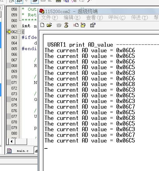
(4) 旋转电位器 R19,可以看到串口输出数值不断变化,正常显示结果如下所示。
usart1 print AD_value ————————–
The current AD value = 0x0425
The current AD value = 0x0423
The current AD value = 0x0421
The current AD value = 0x0422
The current AD value = 0x0420
The current AD value = 0x0416
The current AD value = 0x03B6
The current AD value = 0x0841
The current AD value = 0x08C3
The current AD value = 0x08C0
The current AD value = 0x08BE
The current AD value = 0x09E9
The current AD value = 0x0A12
The current AD value = 0x0ACA
The current AD value = 0x0B0D
The current AD value = 0x0B10
The current AD value = 0x0B0E
….
….
(5) 若无开发板,读者也可以使用
软件
仿真模式来完成程序运行。
下(77.9 KB)